
Introduction | Class 12 Physics Chapter 7 Alternating Current Notes
Welcome back, students. In our previous chapters, like Current Electricity, we mostly dealt with batteries. A battery provides a steady flow of electrons in one single direction. We call that Direct Current (DC). But have you ever wondered about the electricity coming out of the sockets in your wall?
That electricity is quite different. It doesn’t flow steadily; it wiggles! It pushes electrons forward and then pulls them backward, repeating this cycle 50 times every second (in India). This is what we call Alternating Current (AC). In this chapter, we are going to explore why the whole world prefers AC over DC for power transmission, how resistors, capacitors, and inductors behave when you shake the current back and forth, and finally, how we change voltages using Transformers. This is one of the most practical chapters in Physics because it explains the machinery that powers our modern lives. Let’s get started!
1. AC Voltage and Current: The Basics
1.1 What is Alternating Voltage?
Imagine a generator consisting of a coil rotating in a magnetic field. As we learned in Electromagnetic Induction, the flux changes sinusoidally. This produces a voltage that varies with time like a sine wave.
Mathematically, we express this instantaneous voltage $v$ as:
$$v = v_m \sin(\omega t)$$
Here:
- $v_m$ is the peak voltage or amplitude (the maximum height of the wave).
- $\omega$ is the angular frequency ($2\pi \nu$).
- $t$ is the instantaneous time.
If this voltage is applied to a circuit, the resulting current also oscillates:
$$i = i_m \sin(\omega t + \phi)$$
Where $\phi$ is the phase constant, which tells us if the current is in step with the voltage or not.
1.2 Average vs. RMS Value
This is a concept where many students get confused. If I ask you, “What is the average current of an AC cycle?”, you might be tempted to calculate it.
Think about it: For the first half-cycle, the current is positive. For the second half-cycle, it is negative with the exact same magnitude. If you add them up, the average value over one complete cycle is ZERO.
Does that mean AC current delivers zero power? Absolutely not! If you touch a live wire, you get a shock. If you run a heater, it gets hot. The heating effect depends on $i^2$ (Joule’s Heating Law), and the square of a number is always positive.
To measure the “effectiveness” of AC, we use the Root Mean Square (RMS) value. It represents the equivalent DC current that would produce the same amount of heat in a resistor.
The Golden Relation:
$$I_{rms} = I = \frac{i_m}{\sqrt{2}} \approx 0.707 i_m$$
$$V_{rms} = V = \frac{v_m}{\sqrt{2}} \approx 0.707 v_m$$
Teacher’s Tip: When we say the household supply is 220V, we are talking about the RMS value. The peak voltage is actually much higher: $v_m = 220 \times \sqrt{2} \approx 311$ Volts! This is why a 220V AC shock is more dangerous than a 220V DC shock—the peak hits harder.
2. AC Voltage Applied to Basic Components
In DC circuits, a resistor resists, a capacitor blocks current eventually, and an inductor acts like a wire. In AC, things get interesting because the current is constantly changing. We use Phasors (rotating vectors) to visualize the relationship between Voltage ($V$) and Current ($I$).
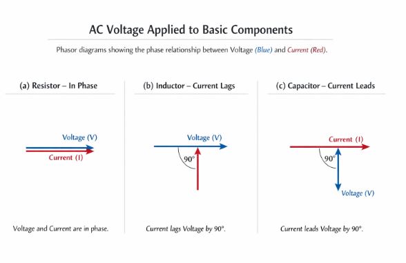
Figure-1: Phasor diagrams showing the phase relationship between Voltage (Blue) and Current (Red). (a) Resistor: In Phase. (b) Inductor: Current lags. (c) Capacitor: Current leads.
2.1 AC Across a Resistor (Purely Resistive)
When AC flows through a resistor, the electrons collide with atoms just like in DC. The current rises and falls exactly at the same time as the voltage.
- Phase Relationship: Voltage and Current are in phase ($\phi = 0$).
- Formula: $v = v_m \sin(\omega t)$ and $i = i_m \sin(\omega t)$.
- Opposition: Resistance $R$.
2.2 AC Across an Inductor (Purely Inductive)
An inductor is a coil. By Lenz’s Law, it opposes any change in current. When AC tries to increase, the inductor pushes back. This causes the current to get “lazy” or delayed.
- Phase Relationship: Current lags behind Voltage by $90^\circ$ ($\pi/2$).
- Opposition (Inductive Reactance): The opposition offered by an inductor is called Inductive Reactance ($X_L$).
$$X_L = \omega L = 2\pi \nu L$$
Notice that if frequency ($\nu$) is zero (DC), $X_L$ is zero. An inductor passes DC easily but blocks high-frequency AC.
2.3 AC Across a Capacitor (Purely Capacitive)
A capacitor consists of two plates separated by a gap. DC cannot cross this gap. But AC charges and discharges the plates. As voltage starts to rise, charge rushes in immediately to fill the plates.
- Phase Relationship: Current leads the Voltage by $90^\circ$ ($\pi/2$).
- Opposition (Capacitive Reactance): The opposition offered by a capacitor is called Capacitive Reactance ($X_C$).
$$X_C = \frac{1}{\omega C} = \frac{1}{2\pi \nu C}$$
If frequency is very high, $X_C$ becomes very small. A capacitor allows high-frequency AC to pass easily but blocks DC completely (since $\nu=0, X_C \to \infty$).
3. The LCR Series Circuit
Now, let’s put all three components—Resistor (R), Inductor (L), and Capacitor (C)—in series connected to an AC source. This is the heart of this chapter.
The Conflict:
- The Resistor wants current and voltage in sync.
- The Inductor wants current to lag by $90^\circ$.
- The Capacitor wants current to lead by $90^\circ$.
Who wins? It depends on the values of $X_L$ and $X_C$.
3.1 Impedance (Z)
Since voltages are not in phase, we cannot simply add them like numbers ($V \neq V_R + V_L + V_C$). We must add them as phasors (vectors).
Using the Pythagorean theorem on the phasor diagram, we find the total opposition, called Impedance ($Z$).
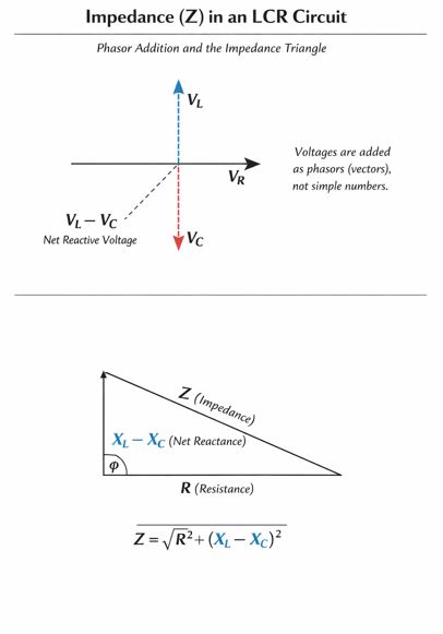
Figure-2: The Impedance Triangle. Resistance (R) is on the base. Net Reactance ($X_L – X_C$) is the altitude. Impedance (Z) is the hypotenuse.
Formula for Impedance:
$$Z = \sqrt{R^2 + (X_C – X_L)^2}$$
The peak current in the circuit is:
$$i_m = \frac{v_m}{Z}$$
3.2 Phase Angle ($\phi$)
The angle by which the total voltage leads or lags the total current is given by:
$$\tan \phi = \frac{X_C – X_L}{R}$$
- If $X_C > X_L$: The circuit acts capacitive (Current leads).
- If $X_L > X_C$: The circuit acts inductive (Current lags).
4. Resonance in LCR Circuits
This is a very special condition. Look at the impedance formula again. $Z$ depends on the difference between $X_C$ and $X_L$.
What if we adjust the frequency such that Inductive Reactance equals Capacitive Reactance ($X_L = X_C$)?
The Magic Happens:
- The net reactance term $(X_C – X_L)$ becomes zero.
- The impedance $Z$ becomes minimum ($Z = \sqrt{R^2 + 0} = R$).
- Since opposition ($Z$) is minimum, the Current becomes Maximum.
Resonant Frequency ($\omega_0$):
Equating $X_L = X_C$:
$$\omega_0 L = \frac{1}{\omega_0 C} \implies \omega_0^2 = \frac{1}{LC}$$
$$\omega_0 = \frac{1}{\sqrt{LC}}$$
or linear frequency $\nu_0 = \frac{1}{2\pi\sqrt{LC}}$.
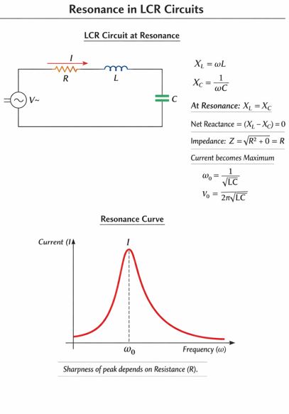
Figure-3: The Resonance Curve. The current peaks sharply at the resonant frequency $\omega_0$. The sharpness depends on the resistance R.
Real-Life Application (Tuning a Radio):
When you turn the knob on an old radio, you are actually changing the capacitance ($C$) of a circuit inside. When the circuit’s natural frequency ($\frac{1}{\sqrt{LC}}$) matches the frequency of the radio station (say, 98.3 MHz), resonance occurs. The current for that specific signal becomes maximum, and you hear the music!
5. Power in AC Circuits
In DC, Power is simply $P = V \times I$. In AC, we have to be careful because $V$ and $I$ might not be peaking at the same time.
The Power Factor:
The average power dissipated in an AC circuit is:
$$P = V_{rms} I_{rms} \cos \phi$$
The term $\cos \phi$ is called the Power Factor.
Analysis:
- Resistor: $\phi = 0^\circ$, so $\cos \phi = 1$. Maximum power is consumed ($P = VI$).
- Pure Inductor/Capacitor: $\phi = 90^\circ$, so $\cos \phi = 0$. Zero power is consumed!
Wattless Current: In a purely inductive or capacitive circuit, current flows, but no work is done over a full cycle. Energy simply shuttles back and forth between the source and the magnetic/electric field. This current is called “Wattless Current”.
6. Transformers
Electricity is generated at power stations far away from cities. If we transmit it at low voltage, the current must be very high ($P=VI$). High current means huge heat loss ($I^2R$) in the transmission wires.
Solution? We step up the voltage to thousands of volts (reducing current) for transmission, and then step it down near your home. The device that does this is the Transformer.
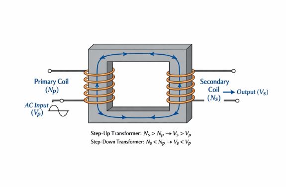
Figure-4: Basic structure of a Transformer showing Primary coil ($N_p$), Secondary coil ($N_s$), and the soft iron core.
Principle: Mutual Induction. An alternating current in the primary coil creates a changing magnetic flux, which is linked to the secondary coil through a soft iron core, inducing a voltage.
The Transformation Ratio:
$$\frac{V_s}{V_p} = \frac{N_s}{N_p} = \frac{I_p}{I_s} = k$$
- Step-Up Transformer: $N_s > N_p$. Increases Voltage, Decreases Current.
- Step-Down Transformer: $N_s < N_p$. Decreases Voltage, Increases Current.
Energy Losses in Transformers:
Real transformers are not 100% efficient. Energy is lost as:
- Flux Leakage: Not all magnetic flux passes from primary to secondary.
- Resistance of Windings ($I^2R$): The copper wire heats up. We use thick wires for high current.
- Eddy Currents: Changing flux induces currents in the iron core itself. We minimize this by using a laminated core.
- Hysteresis Loss: Repeated magnetization and demagnetization of the core generates heat. We use Soft Iron because it has low hysteresis loss.
Common Misconceptions (Teacher’s Note)
- Myth: Electrons in AC move from the power plant to your house.
Fact: No! The electrons just vibrate back and forth in the wire at your home. It’s the energy that travels. - Myth: A capacitor blocks all current.
Fact: A capacitor blocks Direct Current (DC) after charging, but it allows Alternating Current (AC) to flow “through” it (technically, displacement current flows). - Myth: Voltage is always equal to the sum of individual voltages ($V = V_R + V_L + V_C$).
Fact: Incorrect for AC. You must use vector addition (phasors) because they are not peaking at the same time. $V^2 = V_R^2 + (V_L – V_C)^2$.
Practice Set with Solutions
Here are some hand-picked questions based on the latest CBSE trends. Try them before looking at the answers!
Very Short Answer (1 Mark)
Q1. Define the RMS value of alternating current.
Answer: It is the value of steady DC that would produce the same amount of heat in a given resistor as is produced by the AC over a full cycle.
Q2. In a series LCR circuit, the voltage across the inductor, capacitor, and resistor are 20V, 20V, and 40V respectively. What is the phase difference between voltage and current?
Answer: Since $V_L = V_C = 20V$, the circuit is in resonance. The net reactance is zero. The circuit behaves as purely resistive. Hence, the phase difference is zero ($0^\circ$).
Q3. Why is the core of a transformer laminated?
Answer: To reduce energy loss due to Eddy Currents. Laminations break the path of circulating currents in the core.
Short Answer (2-3 Marks)
Q4. Prove that an ideal inductor connected to an AC source dissipates zero average power.
Answer:
Voltage $v = v_m \sin \omega t$.
Current in inductor lags by $\pi/2$, so $i = i_m \sin(\omega t – \pi/2) = -i_m \cos \omega t$.
Instantaneous power $p = vi = -v_m i_m \sin \omega t \cos \omega t = -\frac{v_m i_m}{2} \sin(2\omega t)$.
Average power $P_{avg} = \langle p \rangle$. The average of sine function over a complete cycle is zero.
Therefore, $P_{avg} = 0$.
Q5. A light bulb and a solenoid are connected in series across an AC source. An iron rod is inserted into the solenoid. Explain the effect on the brightness of the bulb.
Answer:
1. When iron is inserted, the magnetic field strengthens, increasing the inductance ($L$) of the solenoid.
2. Inductive reactance $X_L = \omega L$ increases.
3. Total impedance $Z = \sqrt{R^2 + X_L^2}$ increases.
4. Consequently, the current $I = V/Z$ decreases.
5. Since brightness depends on power ($I^2R$), the brightness of the bulb decreases.
Long Answer (5 Marks)
Q6. Derive the expression for the impedance of a series LCR circuit using the phasor diagram method. Find the expression for resonant frequency.
Answer Outline:
1. Draw phasor diagram: $V_R$ along current $I$, $V_L$ leading by $90^\circ$, $V_C$ lagging by $90^\circ$.
2. Resultant voltage $V$ is the vector sum. Horizontal component is $V_R$. Vertical component is $V_L – V_C$ (assuming $V_L > V_C$).
3. Apply Pythagoras: $V^2 = V_R^2 + (V_L – V_C)^2$.
4. Substitute $V=IZ, V_R=IR, V_L=IX_L, V_C=IX_C$.
5. $(IZ)^2 = (IR)^2 + (IX_L – IX_C)^2$.
6. Cancel $I^2$ to get $Z = \sqrt{R^2 + (X_L – X_C)^2}$.
7. For resonance, current is max $\to Z$ is min $\to X_L = X_C$.
8. $\omega L = 1/\omega C \implies \omega = \frac{1}{\sqrt{LC}}$.
Case-Based Question
Q7. The Power Grid and Transmission:
Electrical energy is transmitted over long distances at very high voltages to minimize line losses. A generating station produces power at 440V. This is stepped up to 11,000V for transmission.
(i) What type of transformer is used at the generating station?
(ii) If the primary coil has 100 turns, how many turns are in the secondary?
Answer:
(i) A Step-Up Transformer is used to increase voltage.
(ii) Using ratio $\frac{V_s}{V_p} = \frac{N_s}{N_p}$:
$$N_s = N_p \times \frac{V_s}{V_p} = 100 \times \frac{11000}{440} = 100 \times 25 = 2500 \text{ turns}.$$
Assertion-Reason
Q8. Assertion (A): A capacitor blocks DC but allows AC to pass.
Reason (R): Capacitive reactance is inversely proportional to frequency.
Answer: (A) Both are true and R is the correct explanation.
Explanation: $X_C = \frac{1}{2\pi \nu C}$. For DC, $\nu = 0$, so $X_C = \infty$ (Infinite opposition, acts as open switch). For AC, $\nu$ is finite, so current flows.
Summary & Key Takeaways
- AC Generator: Produces $v = v_m \sin \omega t$.
- RMS Values: $I_{rms} = I_{peak}/\sqrt{2}$. Household 220V is RMS.
- Reactance: $X_L = \omega L$ (increases with freq), $X_C = 1/\omega C$ (decreases with freq).
- Phasors: Current lags voltage in Inductor ($L$), leads in Capacitor ($C$), in phase in Resistor ($R$).
- Resonance: Occurs when $X_L = X_C$. Current is maximum. $\omega_0 = 1/\sqrt{LC}$. Used in tuning radios.
- Power: Only resistors consume power ($P = VI \cos\phi$). $L$ and $C$ consume zero average power.
- Transformer: Works on Mutual Induction. Changes voltage levels. Does not work on DC.
End of Notes.
Students, remember: Draw the phasor diagrams clearly in the exam. Often, a correct diagram fetches you partial marks even if the calculation goes slightly wrong!
Read Also:
Class-12 Chapter 6- Electromagnetic Induction
For more check official website of
NCERT