
Start Chapter MCQ Quiz
Comprehensive Guide: Class 12 Physics Chapter 6 Electromagnetic Induction Notes
1. Introduction: The Symmetry of Nature| Class 12 Physics Chapter 6 Electromagnetic Induction Notes
Hello students! Welcome to one of the most revolutionary chapters in Class 12 Physics. Have you ever wondered how the electricity that powers the device you are reading this on is actually generated? It doesn’t come from batteries; it comes from giant turbines spinning in power plants. But how does spinning a wheel create electricity? The answer lies in Electromagnetic Induction.
Let’s take a step back to the early 19th century. In previous chapters (Moving Charges and Magnetism), you learned about a groundbreaking discovery made by Oersted and Ampere: Electric current produces a magnetic field. This was a huge deal! It meant that electricity could turn into magnetism.
But physicists are thinkers who love symmetry. They asked a simple but profound question: “If electricity can produce magnetism, can magnetism produce electricity?”
For years, the answer seemed to be “No.” You can place a strong magnet next to a wire for 100 years, and no current will flow. However, around 1830, two scientists—Michael Faraday in the UK and Joseph Henry in the USA—independently discovered the missing ingredient. They found that a stationary magnet does nothing, but a moving or changing magnetic field can indeed wake up the electrons in a wire and make them move.
This phenomenon, where a changing magnetic field induces an electric current in a closed circuit, is called Electromagnetic Induction. It is the fundamental principle behind generators, transformers, induction cooktops, and even the wireless charging of your smartphone. Let’s explore this magic!
2. Faraday’s Experiments: The Discovery
Faraday was a master experimentalist. He didn’t start with math; he started with observation. To understand this chapter, you must visualize his three famous experiments. These are often asked in board exams to test your conceptual understanding.
Experiment 6.1: Current Induced by a Magnet
Imagine a coil of wire connected to a Galvanometer (G). A galvanometer is a sensitive device that detects very small currents. Note that there is no battery in this circuit.
- Action 1: Faraday pushed the North Pole of a bar magnet towards the coil.
Observation: The galvanometer needle deflected momentarily. This indicated that a current was flowing! - Action 2: He stopped the magnet inside the coil.
Observation: The deflection dropped to zero immediately. Even though the magnet was inside the strong field, no current flowed because there was no motion. - Action 3: He pulled the North Pole away from the coil.
Observation: The needle deflected again, but in the opposite direction. - Action 4: He moved the magnet faster.
Observation: The deflection was much larger.
Teacher’s Note: This experiment proved that it is not the magnetic field itself that creates current, but the relative motion between the magnet and the coil.

Figure-1: When the magnet moves towards the coil, current flows. When it stops, current stops. Faster motion creates more current.
Experiment 6.2: Current Induced by Another Current
Faraday wondered: “Do I need a permanent magnet, or can an electromagnet work?” He replaced the bar magnet with a second coil (let’s call it the Primary Coil, $C_2$) connected to a battery. A steady current flowed through $C_2$, creating a magnetic field around it.
The Result: When he moved coil $C_2$ towards or away from the galvanometer-coil ($C_1$), the exact same induction happened.
Conclusion: It doesn’t matter what creates the magnetic field. As long as the magnetic field passing through coil $C_1$ is changing due to motion, current is induced.
Experiment 6.3: Induction by Changing Current (No Motion)
This is the most critical experiment. Faraday placed two coils side-by-side but did not move them.
- Coil 2 was connected to a battery and a Tapping Key (Switch).
- Coil 1 was connected to a Galvanometer.
Observation:
- When he pressed the key, the galvanometer in Coil 1 showed a momentary jolt.
- While he held the key down (steady current), the galvanometer showed zero.
- When he released the key, the galvanometer showed a momentary jolt in the opposite direction.
Explanation: When you switch on a circuit, current doesn’t jump to maximum instantly; it takes a split second to rise. During this rise, the magnetic field is growing. This changing magnetic field induces the current. Once the current is steady, the field is constant, so induction stops. When you switch off, the field collapses (changes again), inducing a reverse current.
3. Magnetic Flux ($\Phi_B$): The Mathematical Tool
To formulate a law, Faraday needed to quantify “how much magnetic field” is passing through the coil. We use the concept of Magnetic Flux.
Imagine holding a ring in flowing water. The amount of water passing through the ring depends on three things:
1. The speed of the water (Magnetic Field Strength, $B$).
2. The size of the ring (Area, $A$).
3. The angle at which you hold the ring against the flow (Orientation, $\theta$).
Definition: Magnetic Flux ($\Phi_B$) through a plane surface is the dot product of the magnetic field vector and the area vector.
$$\Phi_B = \vec{B} \cdot \vec{A} = BA \cos\theta$$
Students often get the angle $\theta$ wrong!
$\theta$ is the angle between the Magnetic Field ($\vec{B}$) and the Area Vector ($\vec{A}$). The Area Vector is always perpendicular (normal) to the surface of the coil.
- Case 1: Coil is held perpendicular to the field. Normal is parallel to field. $\theta = 0^\circ$. Flux is Maximum ($BA$).
- Case 2: Coil is held parallel to the field. Normal is at $90^\circ$. $\theta = 90^\circ$. Flux is Zero.
Unit: The SI unit of magnetic flux is the Weber (Wb).
$$1 \text{ Wb} = 1 \text{ Tesla-meter}^2$$
4. Faraday’s Law of Electromagnetic Induction
Based on his experiments, Faraday gave us one of the most important equations in physics.
The Law States: The magnitude of the induced electromotive force (emf) in a circuit is directly proportional to the time rate of change of magnetic flux through the circuit.
The Formula:
$$\varepsilon = – \frac{d\Phi_B}{dt}$$
If the coil has $N$ tightly wound turns, the flux change happens in each turn, so the effects add up:
$$\varepsilon = – N \frac{d\Phi_B}{dt}$$
Breaking Down the Equation:
- $\varepsilon$: Induced EMF (Voltage). It behaves like a battery. If the circuit is closed, a current $I = \varepsilon/R$ flows.
- $d\Phi_B/dt$: This represents the speed of change. A faster change creates a larger voltage. This explains why moving the magnet faster in Experiment 6.1 gave a larger deflection.
- The Negative Sign ($- $): This is not just a mathematical decoration. It represents the direction of the induced emf, which brings us to Lenz’s Law.
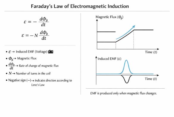
Figure-2: Notice that EMF is non-zero only when the Flux is changing (sloped line). If Flux is constant (flat line), EMF is zero.
Ways to Induce EMF
Since Flux $\Phi = BA \cos\theta$, we can induce electricity by changing any of these three variables:
- Changing B: Move a magnet closer/farther, or change current in a nearby solenoid.
- Changing A: Shrink, stretch, or deform the coil inside a magnetic field.
- Changing $\theta$: Rotate the coil inside a magnetic field. This is the principle of AC Generators.
5. Lenz’s Law: The Law of Nature’s Stubbornness
While Faraday gave us the magnitude of induced emf, Heinrich Lenz gave us the direction. Lenz’s law is essentially the “Law of Karma” or “Newton’s Third Law” applied to electricity.
Statement: The polarity of the induced emf is such that it tends to produce a current which opposes the change in magnetic flux that produced it.
In Simple Teacher Language:
The coil “hates” change.
- If magnetic flux is increasing, the coil creates a current to decrease it.
- If magnetic flux is decreasing, the coil creates a current to increase it.
Example: The Approaching Magnet
Imagine pushing the North Pole of a magnet towards a coil.
The Change: Magnetic flux through the coil is increasing.
The Opposition: The coil wants to stop the magnet from coming closer. How can it repel a North Pole? By becoming a North Pole itself!
The Result: The induced current flows Counter-Clockwise (which creates a North face) to repel the magnet.
Conversely, if you pull the North Pole away, the flux decreases. The coil wants to stop it from leaving. It becomes a South Pole (Clockwise current) to attract the magnet back.
Does Lenz’s Law Violate Energy Conservation?
Students often ask this. The answer is NO. In fact, Lenz’s Law is a direct consequence of the Conservation of Energy.
Think about it: Imagine if Lenz’s law were reversed. If you pushed a magnet towards a coil and the coil became a South Pole, it would attract the magnet. The magnet would speed up, inducing more current, creating stronger attraction, speeding up even more…
You would get infinite kinetic energy and infinite electrical energy from a tiny push! This is a “Perpetual Motion Machine,” which is physically impossible.
The Reality: Because of Lenz’s opposition (Repulsion), you have to do Mechanical Work to push the magnet against the repulsive force. It is this mechanical work that gets converted into Electrical Energy (and heat). Nothing is free in nature!
6. Motional Electromotive Force (Motional EMF)
So far, we discussed stationary coils and changing fields. Now, let’s consider a conductor moving through a magnetic field. This is arguably the easiest way to visualize induction.
Consider a rectangular conducting loop where one side (a rod of length $l$) is free to slide. The setup is placed in a uniform magnetic field $B$. We move the rod with velocity $v$.
Derivation using Faraday’s Law:
As the rod moves, the area of the rectangular loop changes.
$$\text{Flux } \Phi = B \times \text{Area} = B(lx)$$
Where $x$ is the width of the loop.
$$\varepsilon = – \frac{d\Phi}{dt} = – \frac{d(Blx)}{dt} = -Bl \frac{dx}{dt}$$
Since the speed $v = -dx/dt$ (distance is decreasing), we get:
$$\varepsilon = Blv$$
This is the formula for Motional EMF.
Alternative View: Lorentz Force
We can explain this without flux! Inside the conducting rod, there are free electrons. If the rod moves at velocity $v$, the electrons are also moving at velocity $v$.
A charge $q$ moving in a magnetic field experiences a Lorentz Force:
$$F = q(\vec{v} \times \vec{B})$$
The magnitude is $F = qvB$ (if $v \perp B$).
This force pushes electrons to one end of the rod, creating a potential difference.
$$\text{Work done} = \text{Force} \times \text{Distance} = (qvB) \times l$$
$$\text{EMF} = \frac{\text{Work}}{\text{Charge}} = \frac{qvBl}{q} = Blv$$
Both methods give the exact same result. Physics is beautiful!
7. Eddy Currents: The Swirling Electricity
What happens if, instead of a wire loop, we move a solid bulk piece of metal (like a copper plate) in a magnetic field?
The changing flux still induces currents, but since there is no defined wire path, the currents swirl around in loops inside the metal, looking like eddies (whirlpools) in water. These are called Eddy Currents (discovered by Foucault).
Effects of Eddy Currents:
- Heating: Since the metal has resistance, these large currents produce significant heat ($I^2R$). This is used in Induction Furnaces to melt metals.
- Damping (Braking): According to Lenz’s law, eddy currents oppose the motion. If a metal plate swings between magnets, the eddy currents create a magnetic drag that stops the plate quickly.
Real Life Applications:
- Magnetic Braking in Trains: Modern electric trains use electromagnets to induce eddy currents in the rails, creating a smooth, contact-less braking force.
- Speedometers: In analog cars, a rotating magnet induces eddy currents in a drum, dragging the needle to show speed.
- Induction Cooktops: Rapidly changing magnetic fields induce eddy currents in the base of your steel pot, heating the food directly.
8. Inductance: Electrical Inertia
In mechanics, you learned about “Inertia” (Mass). Inertia is the property of a body to oppose any change in its velocity. In electricity, we have an analogue called Inductance. It opposes any change in current.
8.1 Self-Inductance (L)
Consider a single isolated coil. When you switch on a battery connected to it, the current starts to rise from 0 to I.
This rising current creates a rising magnetic field. This rising magnetic field passes through the same coil!
According to Lenz’s law, the coil “hates” this change. It induces a voltage (Back EMF) to fight the rising current. This phenomenon is called Self-Induction.
Formula:
$$\Phi \propto I \Rightarrow \Phi = LI$$
$$\varepsilon = -L \frac{dI}{dt}$$
Here, $L$ is the Coefficient of Self-Inductance. Its unit is the Henry (H).
Energy in Inductor: To overcome this back EMF and establish current, the battery does work. This work is stored as Magnetic Potential Energy.
$$U = \frac{1}{2} L I^2$$
(Notice the similarity to Kinetic Energy $K = \frac{1}{2} mv^2$. $L$ acts like mass $m$, $I$ acts like velocity $v$).
8.2 Mutual Inductance (M)
If two coils are placed close to each other, a changing current in Coil 1 creates a changing flux in Coil 2.
$$\Phi_2 = M I_1$$
$$\varepsilon_2 = -M \frac{dI_1}{dt}$$
This is the principle behind Transformers, which we will study in the next chapter.
9. The AC Generator: Powering the World
This is the technological climax of the chapter. We use the principle of induction to convert mechanical energy into electrical energy on a massive scale.
Construction:
It consists of a rectangular coil (Armature) rotating between two strong magnetic poles. The ends of the coil are connected to Slip Rings and Carbon Brushes.
Working Principle:
As the coil rotates with angular velocity $\omega$, the angle $\theta$ between the area vector and magnetic field changes continuously ($\theta = \omega t$).
Flux $\Phi = NBA \cos(\omega t)$.
Using Faraday’s Law:
$$\varepsilon = – \frac{d\Phi}{dt} = – \frac{d}{dt} (NBA \cos \omega t)$$
$$\varepsilon = NBA \omega \sin(\omega t)$$
$$\varepsilon = \varepsilon_0 \sin(\omega t)$$
Why AC?
Since the function depends on $\sin(\omega t)$, the voltage oscillates between positive and negative values. This is why the current produced is Alternating Current (AC). The direction of current changes every half rotation.
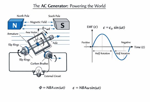
Figure-3: The AC Generator. As the coil rotates, the orientation changes, producing a sine-wave voltage output.
Solved Numericals (Board Exam Style)
Numerical 1: Faraday’s Law
Question: A circular coil of radius 10 cm, 500 turns, and resistance 2 $\Omega$ is placed with its plane perpendicular to the horizontal component of the earth’s magnetic field. It is rotated about its vertical diameter through $180^\circ$ in 0.25 s. Estimate the magnitudes of the emf and current induced. (Given $H_E = 3.0 \times 10^{-5}$ T).
Solution:
1. Identify Givens:
$N = 500$, $R = 2 \Omega$, $r = 10 \text{ cm} = 0.1 \text{ m}$.
$B = 3.0 \times 10^{-5}$ T.
$dt = 0.25$ s.
Area $A = \pi r^2 = \pi (0.1)^2 = 0.01\pi \text{ m}^2$.
2. Initial Flux ($\Phi_i$):
Coil is perpendicular to field $\rightarrow \theta_1 = 0^\circ$.
$\Phi_i = NBA \cos 0^\circ = 500 \times (3 \times 10^{-5}) \times (0.01\pi) \times 1$.
$\Phi_i = 15 \pi \times 10^{-5}$ Wb.
3. Final Flux ($\Phi_f$):
Rotated by $180^\circ \rightarrow \theta_2 = 180^\circ$.
$\Phi_f = NBA \cos 180^\circ = -NBA$.
$\Phi_f = -15 \pi \times 10^{-5}$ Wb.
4. Change in Flux ($d\Phi$):
$d\Phi = \Phi_f – \Phi_i = -15\pi \times 10^{-5} – (15\pi \times 10^{-5}) = -30\pi \times 10^{-5}$ Wb.
5. Induced EMF:
$|\varepsilon| = \frac{|d\Phi|}{dt} = \frac{30\pi \times 10^{-5}}{0.25} = 120\pi \times 10^{-5} \approx 3.8 \times 10^{-3}$ V = 3.8 mV.
6. Current:
$I = \varepsilon / R = 3.8 \text{ mV} / 2 \Omega = 1.9 \text{ mA}$.
Numerical 2: Motional EMF (The Jet Plane Problem)
Question: A jet plane is travelling towards the west at a speed of 1800 km/h. What is the voltage difference developed between the ends of the wing having a span of 25 m, if the Earth’s magnetic field at the location has a magnitude of $5 \times 10^{-4}$ T and the dip angle is $30^\circ$?
Solution:
This is a classic question. The wings are horizontal. The plane moves West.
The wings “cut” the magnetic field lines. But which component?
Since the wings move horizontally, they cut the Vertical Component ($B_V$) of Earth’s field.
1. Calculate $B_V$:
$B_V = B \sin(\delta)$ where $\delta$ is dip angle.
$B_V = 5 \times 10^{-4} \times \sin(30^\circ) = 2.5 \times 10^{-4}$ T.
2. Convert Speed:
$v = 1800 \text{ km/h} = 1800 \times \frac{5}{18} = 500 \text{ m/s}$.
3. Apply Motional EMF Formula:
$\varepsilon = B_V l v$
$\varepsilon = (2.5 \times 10^{-4}) \times (25) \times (500)$
$\varepsilon = 3.125$ Volts.
Practice Set: Test Your Knowledge
Very Short Answer (1 Mark)
Q1. The electric current flowing in a wire in the direction from B to A is decreasing. What is the direction of induced current in the metallic loop placed above the wire?
Ans: The current in the straight wire produces a magnetic field. Since current is decreasing, the flux through the loop is decreasing. By Lenz’s law, the loop will induce a current to support the dying field. (Answer depends on specific orientation, usually same direction as source wire if parallel).
Short Answer (2 Marks)
Q2. A plot of magnetic flux ($\Phi$) versus current ($I$) is shown for two inductors A and B. Which of the two has a larger value of self-inductance?
Ans: We know $\Phi = LI$. This is the equation of a straight line $y = mx$ where slope $m = L$. The line with the steeper slope has higher inductance. (Check the graph provided in exam).
Long Answer (5 Marks)
Q3. Derive the expression for Mutual Inductance of two long coaxial solenoids.
Hint for Solution:
1. Assume current $I_2$ in outer solenoid.
2. Calculate $B_2 = \mu_0 n_2 I_2$.
3. Calculate Flux in inner solenoid $\phi_1 = B_2 A_1$.
4. Total Flux $N_1 \phi_1$.
5. Equate to $M I_2$.
Result: $M = \mu_0 n_1 n_2 \pi r_1^2 l$.
Final Note: Electromagnetic Induction is the bridge between electricity and magnetism. Master Lenz’s Law—if you can figure out the direction correctly, the rest is just algebra! Good luck with your preparation.
Read Also:
Class-12 Chapter 5- Magnetism and Matter
For more check official website of
NCERT