
Introduction | Welcome to the World of Waves
Hello students! In our previous lessons, we studied Ray Optics, where we assumed that light travels in perfectly straight lines. We used this idea to understand mirrors, lenses, and prisms. But today, we are going to look at light from a completely different perspective.
Imagine you are hiding behind a thick wall. If someone is talking on the other side, you can hear them perfectly well, even though you cannot see them. Why is that? It is because sound waves can bend around corners.
If light travels purely in straight lines, it shouldn’t bend around corners either, right? But what if I told you that light does bend around obstacles if they are small enough? To explain these magical phenomena—like the rainbow colors you see on a soap bubble or a CD—we have to stop treating light as a straight-moving particle and start treating it as a wave. Let’s dive into the fascinating journey of Wave Optics!
1. The Great Debate: Particle vs. Wave
1.1 Newton’s Corpuscular Theory
A long time ago, the brilliant scientist Isaac Newton supported the “Corpuscular Theory” of light. According to this theory, light consists of tiny, elastic particles called corpuscles. Because Newton was such a respected figure in science, almost everyone believed him. His theory successfully explained reflection and refraction.
However, Newton’s theory made one critical prediction: it stated that when light travels from a rarer medium (like air) to a denser medium (like water) and bends towards the normal, its speed must increase. Keep this in mind, because it becomes the ultimate test!
1.2 Huygens’ Wave Theory
Around the same time, a Dutch physicist named Christiaan Huygens proposed a completely different idea. He argued that light is not made of particles, but is actually a wave. His wave theory could also explain reflection and refraction. But here was the twist: Huygens’ theory predicted that when light enters a denser medium, its speed should decrease.
For over a century, people ignored Huygens because of Newton’s immense popularity. It wasn’t until the 1800s, when Thomas Young performed his famous interference experiment, that the scientific world realized light truly behaves like a wave. Later, a scientist named Foucault experimentally measured the speed of light in water and found it was indeed slower than in air. Huygens was right all along! Eventually, James Clerk Maxwell proved that these waves are electromagnetic in nature, meaning they don’t even need a physical medium to travel through space.
2. Wavefronts and Huygens’ Principle
To understand wave optics, we first need to learn the language of waves. The most important concept here is the “Wavefront.”
2.1 What is a Wavefront?
Let’s use a daily life example. Imagine dropping a stone into a calm pond. What do you see? You see circular ripples spreading outwards. If you take a photograph of the water at any exact second, you will see rings where the water is at its highest point (crests). Every single drop of water on that specific ring is moving exactly in sync; we say they are oscillating in the same “phase.”
Definition: A wavefront is defined as the continuous locus of all points in a medium that are vibrating in the same phase.
The direction in which the wave travels (the light ray) is always strictly perpendicular to the wavefront.
- Spherical Wavefront: If you have a tiny point source of light (like a small LED bulb), the light spreads out uniformly in all 3D directions. The wavefronts are concentric spheres.
- Plane Wavefront: If you look at a spherical wavefront from a very, very long distance (like light coming from the Sun), a small portion of that huge sphere looks perfectly flat. We call this a plane wavefront.
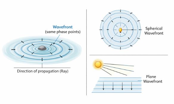
Figure-1: A point source generating spherical wavefronts. As distance increases, a small section of the spherical wave approximates a plane wave. Notice how the rays are perpendicular to the wavefronts.
2.2 Huygens’ Principle Explained
Huygens gave us a beautiful geometric trick. If you know what a wavefront looks like right now, how do you find out where it will be 2 seconds from now? Here are his two golden rules:
- Every point on a given wavefront acts as a fresh source of new disturbance. These new disturbances are called “secondary wavelets,” and they spread out in all directions with the speed of light in that medium.
- The new wavefront at any later time is simply the forward envelope (or common tangent) of all these secondary wavelets.
Teacher’s Note: You might wonder, if wavelets spread in all directions, why doesn’t light travel backward? Huygens assumed the amplitude of the backward wave is zero. Later, advanced mathematics proved that the backward wave naturally cancels itself out.
3. Proving Laws of Refraction Using Huygens’ Principle
This is one of the most frequently asked derivations in the board exams. Pay close attention to the geometry!
Let us imagine a plane wavefront hitting a boundary between two mediums (say, air to glass) at an angle. Medium 1 has a light speed of $v_1$ and Medium 2 has a light speed of $v_2$. Let’s assume Medium 2 is denser, so $v_2 < v_1$.
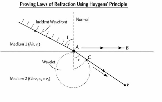
Figure-2: Huygens’ construction for refraction. The incident wavefront AB bends to form the refracted wavefront CE because light travels slower in the second medium.
The Derivation Steps:
- Consider an incident plane wavefront AB hitting the surface at angle $i$.
- Point A touches the boundary first. While point B is still traveling in Medium 1 to reach point C, point A immediately starts generating secondary wavelets in Medium 2.
- Let the time taken for light to travel from B to C be $\tau$. Therefore, the distance $BC = v_1 \tau$.
- In this exact same time $\tau$, the wavelet from A travels a distance in Medium 2 equal to $v_2 \tau$. We draw a sphere of radius $v_2 \tau$ from point A.
- Draw a tangent from C to this sphere. Let the tangent point be E. CE is our new refracted wavefront!
Now, look at the two triangles in the diagram: $\Delta ABC$ and $\Delta AEC$.
In $\Delta ABC$:
$$\sin i = \frac{BC}{AC} = \frac{v_1 \tau}{AC}$$
In $\Delta AEC$:
$$\sin r = \frac{AE}{AC} = \frac{v_2 \tau}{AC}$$
Dividing the two equations, the $AC$ and $\tau$ cancel out perfectly:
$$\frac{\sin i}{\sin r} = \frac{v_1}{v_2}$$
We know that the absolute refractive index is defined as $n = c/v$. Therefore, $v_1 = c/n_1$ and $v_2 = c/n_2$. Substituting these in:
$$\frac{\sin i}{\sin r} = \frac{n_2}{n_1}$$
$$n_1 \sin i = n_2 \sin r$$
Boom! This is Snell’s Law. We just proved a core law of ray optics using pure wave geometry.
A Crucial Teacher’s Tip: When light goes from air to water, its speed drops, and its wavelength shrinks. BUT, its frequency never changes! Why? Because frequency is the “heartbeat” of the source. Once the light leaves the source, the number of waves created per second is locked.
4. The Principle of Superposition and Interference
What happens when two light waves meet at the exact same spot at the exact same time? Do they crash and destroy each other? No, they add up. This is the Principle of Superposition.
If Wave 1 creates a displacement $y_1$ and Wave 2 creates a displacement $y_2$, the net displacement is simply their vector sum: $y = y_1 + y_2$.
4.1 Constructive and Destructive Interference
Imagine two coherent sources (sources that maintain a constant phase difference, like two precisely synchronized vibrating needles in water).
- Constructive Interference: If the crest of Wave 1 perfectly overlaps with the crest of Wave 2, they team up. The amplitude doubles, and the spot becomes incredibly bright. This happens when the path difference between the two waves is a full number of wavelengths: $\Delta x = n\lambda$ (where $n = 0, 1, 2…$).
- Destructive Interference: If the crest of Wave 1 meets the trough of Wave 2, they fight and cancel each other out. The spot becomes completely dark. This happens when the path difference is a half-step: $\Delta x = (n + \frac{1}{2})\lambda$.
The Intensity Formula:
If both sources produce light of intensity $I_0$, the resultant intensity $I$ at any point depends on the phase difference $\phi$ between them:
$$I = 4I_0 \cos^2\left(\frac{\phi}{2}\right)$$
When they are in phase ($\phi = 0$), $I = 4I_0$ (Maximum brightness!). When they are out of phase ($\phi = 180^\circ$), $I = 0$ (Total darkness).
Why don’t we see interference with two separate light bulbs?
Because normal light bulbs are “incoherent.” Their atoms emit light randomly in bursts that last $10^{-10}$ seconds. The phase difference changes billions of times a second! Our eyes are too slow to see the flickering, so we just see an average smeared-out brightness ($I = 2I_0$).
5. Young’s Double Slit Experiment (YDSE)
Thomas Young was a genius. He figured out a way to create two perfectly coherent sources of light to prove the wave theory once and for all.
Instead of using two different bulbs, Young took one light source and let it pass through a single slit. Then, he placed a barrier with two tiny slits ($S_1$ and $S_2$) right in front of the spreading wavefront. Because the light coming out of $S_1$ and $S_2$ originally came from the exact same parent source, any random phase jump in the parent happens to both $S_1$ and $S_2$ simultaneously. Thus, they act as perfectly coherent sources!
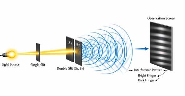
Figure-3: Young’s Double Slit setup. The overlapping waves from $S_1$ and $S_2$ create a beautiful pattern of alternating bright and dark fringes on the observation screen.
5.1 Calculating Fringe Positions
Let the distance between the two slits be $d$, and the distance to the screen be $D$. For a point $P$ on the screen at a height $x$ from the center, the path difference between the waves from $S_2$ and $S_1$ can be geometrically approximated as:
$$\text{Path Difference} = \frac{xd}{D}$$
For Bright Fringes (Maxima):
Path difference must be $n\lambda$.
$$\frac{xd}{D} = n\lambda \implies x_n = \frac{n\lambda D}{d}$$
(where $n = 0, \pm1, \pm2…$)
For Dark Fringes (Minima):
Path difference must be $(n + \frac{1}{2})\lambda$.
$$\frac{xd}{D} = \left(n + \frac{1}{2}\right)\lambda \implies x_n = \left(n + \frac{1}{2}\right)\frac{\lambda D}{d}$$
Fringe Width ($\beta$):
The distance between two consecutive bright fringes (or two dark fringes) is constant. This is a very important formula for numericals!
$$\beta = \frac{\lambda D}{d}$$
Teacher’s logic: If you use red light (longer wavelength) instead of blue light, the fringes will become wider and more spread out. If you move the screen further away (increase D), the pattern expands.
6. Diffraction: Light Bending Around Corners
Have you ever noticed that shadows aren’t perfectly sharp? If you look closely at the edge of a shadow cast by a sharp blade, it has tiny, fuzzy lines of bright and dark bands. This isn’t poor eyesight—this is Diffraction.
Diffraction is the bending of waves around the corners of an obstacle or an aperture. It happens with all waves (sound, water), but for light, we rarely notice it because light’s wavelength is extremely tiny (around $0.5 \text{ \mu m}$). Diffraction only becomes noticeable when the size of the obstacle or hole is comparable to the wavelength of the light.
6.1 Single Slit Diffraction
If we shine a laser beam through one single, narrow slit of width $a$, we don’t just see a single straight line of light on the wall. Instead, the light spreads out! We see a huge, bright central region, flanked by smaller, fading bright and dark bands on either side.
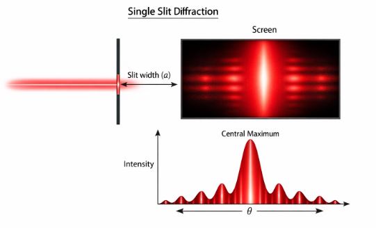
Figure-4: Intensity distribution for a single slit. Notice how the central maximum is much wider and brighter than the secondary maxima.
The Math of the Single Slit:
To understand this, we divide the single slit into tiny mathematical point sources (using Huygens’ principle). We find that the condition for complete darkness (Minima) occurs at angles $\theta$ where:
$$\theta = \frac{n\lambda}{a}$$
(where $n = \pm1, \pm2, \pm3…$ but NEVER 0).
At $\theta = 0$, all the wavelets arrive perfectly in phase, creating the massive Central Maximum.
The angular width of this central bright spot is $\frac{2\lambda}{a}$.
Interference vs. Diffraction: What’s the difference?
As the great physicist Richard Feynman said, there is no deep physical difference—they both rely on the superposition of waves! However, conventionally, we say “Interference” when we have a few specific sources (like 2 slits), and “Diffraction” when we have a continuous, infinite number of sources (like the infinite points across one single slit).
7. Polarisation: The Transverse Nature of Light
Up until now, we’ve treated light as a wave without asking: What kind of wave? Is it like a sound wave (pushing and pulling backward and forward) or like a string wave (wiggling up and down)?
Light is a Transverse Electromagnetic Wave. This means the electric and magnetic fields are vibrating strictly perpendicular to the direction the light is traveling.
Normal light (like sunlight or a lightbulb) is Unpolarised. Think of a string that is vibrating up and down, left and right, and diagonally all at the same time in random, rapid bursts. The electric field vector takes all possible directions perpendicular to the travel path.
7.1 Polaroids and Plane Polarised Light
A “Polaroid” is a special plastic sheet made of long-chain molecules aligned parallel to each other. When unpolarised light hits this sheet, the molecules absorb the electric vibrations that are parallel to them. Only the vibrations perpendicular to the molecules are allowed to pass. This allowed direction is called the Pass-Axis.
The light that makes it through is now perfectly Linearly Polarised (or Plane Polarised)—it is vibrating in only one single, neat direction. Because we stripped away half the random vibrations, the intensity of the light drops exactly by half: $I = I_0 / 2$.
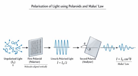
Figure-5: Two polaroids in sequence. The first acts as a polariser, halving the intensity. The second acts as an analyser, and its rotation controls the final light output according to Malus’ Law.
7.2 Malus’ Law
What happens if we put a second Polaroid (called an analyser) behind the first one? If the pass-axis of the second polaroid is at an angle $\theta$ relative to the first one, it will only let the component of the electric field ($E \cos\theta$) through. Since intensity is proportional to the square of the amplitude, we get Malus’ Law:
$$I = I_0 \cos^2\theta$$
If the two polaroids are parallel ($\theta = 0^\circ$), all light passes. If they are “crossed” ($\theta = 90^\circ$), the light is completely blocked, and you see total darkness!
Real-Life Examples (CBSE Context)
- Anti-Reflection Coatings on Glasses: Thin films on your spectacles use destructive interference to cancel out reflecting light rays, making your lenses clear and glare-free.
- Colors on an Oil Slick or CD: The rainbow patterns you see are not from pigments; they are due to interference and diffraction of white light bouncing off closely spaced microscopic grooves or thin layers of oil.
- 3D Movies: Have you worn 3D glasses at the cinema? Those are simply polaroid lenses! The projector displays two slightly different images with perpendicular polarisations. One lens of your glasses lets the vertical light in (for the left eye) and blocks the horizontal, while the other lens does the opposite. Your brain fuses them to see 3D!
- Sunglasses and Photography: Photographers use polarising filters on camera lenses to block out the harsh, horizontally polarised glare reflecting off water or glass surfaces, revealing what’s underneath.
Common Student Misconceptions (Teacher’s Warning!)
- Mistake: Thinking speed determines the energy of the light wave.
Correction: Energy depends on the amplitude (or frequency in the photon model), not the speed of propagation. Slowing down in glass doesn’t mean the wave loses energy! - Mistake: Thinking wavelength stays constant during refraction.
Correction: When light enters water, it slows down ($v$ decreases), so the wavefronts get squished closer together ($\lambda$ decreases). But the frequency $f$ remains strictly constant! - Mistake: Confusing the formulas for YDSE and Single Slit.
Correction: In YDSE, $\Delta x = n\lambda$ gives bright fringes. In Single Slit, $\theta = n\lambda/a$ gives dark fringes. Don’t mix them up in the exam!
Important Board Exam Derivations Summary
Before your exam, make sure you can derive these on paper with clear diagrams:
- Refraction using Huygens’ Principle: Draw the wavefronts carefully. Show the $v_1 \tau$ and $v_2 \tau$ triangles to prove $\sin i / \sin r = v_1/v_2$.
- Fringe Width in YDSE: Start with path difference $xd/D$, equate to $n\lambda$, and subtract $x_n$ from $x_{n+1}$ to prove $\beta = \lambda D/d$.
- Malus’ Law understanding: Show how the electric field vector splits into $E \cos\theta$ and $E \sin\theta$, and why squaring it gives the intensity function.
CBSE Practice Set with Solutions
Test your understanding with these exam-style questions.
Very Short Answer Type (1 Mark)
Q1. What is the shape of the wavefront emerging from a distant star intercepted by Earth?
Solution: A plane wavefront. Because the star is at a very large distance, a small intercepted portion of its spherical wavefront appears flat.
Q2. Two independent sodium lamps are used to illuminate two slits in a YDSE setup. Will you observe an interference pattern?
Solution: No. Two separate sources are incoherent. They will not maintain a constant phase difference, resulting in an average uniform illumination rather than distinct fringes.
Short Answer Type (2-3 Marks)
Q3. Monochromatic light of wavelength 589 nm is incident from air on a water surface. The refractive index of water is 1.33. Find the wavelength and frequency of the refracted light. (Speed of light in vacuum = $3 \times 10^8 \text{ m/s}$)
Solution:
1. Frequency ($f$) remains constant across mediums.
$f = \frac{c}{\lambda_{air}} = \frac{3 \times 10^8}{589 \times 10^{-9}} = 5.09 \times 10^{14} \text{ Hz}$.
2. Wavelength in water ($\lambda_{water}$) changes according to the refractive index.
$\lambda_{water} = \frac{\lambda_{air}}{n} = \frac{589}{1.33} = 442.8 \text{ nm}$.
Q4. In a Young’s double-slit experiment, the slits are separated by 0.28 mm and the screen is 1.4 m away. The distance between the central bright fringe and the fourth bright fringe is 1.2 cm. Determine the wavelength of light used.
Solution:
Given: $d = 0.28 \times 10^{-3} \text{ m}$, $D = 1.4 \text{ m}$, $x_4 = 1.2 \times 10^{-2} \text{ m}$, $n = 4$.
Formula for nth bright fringe: $x_n = \frac{n\lambda D}{d}$
Rearranging for wavelength: $\lambda = \frac{x_n \times d}{n \times D}$
$\lambda = \frac{1.2 \times 10^{-2} \times 0.28 \times 10^{-3}}{4 \times 1.4}$
$\lambda = 6 \times 10^{-7} \text{ m} = 600 \text{ nm}$.
Long Answer Type (5 Marks)
Q5. (a) State Huygens’ principle. (b) Use this principle to draw a diagram showing the propagation of a plane wavefront passing through a thin convex lens. (c) Why does the wavefront change its shape?
Solution:
(a) Huygens’ principle states that every point on a wavefront acts as a secondary source emitting wavelets in all directions. The new wavefront is the forward tangential envelope of these secondary wavelets.
(b) (Student must draw a straight vertical line for the incident plane wavefront, hitting a biconvex lens, and emerging as a curved, converging spherical wavefront pointing toward the focus.)
(c) The speed of light is slower in the glass lens than in air. The central part of the plane wavefront has to travel through the thickest part of the glass, so it gets delayed the most. The edges travel through thin glass and exit faster. This uneven delay causes the flat wavefront to curve inward (converge) and become spherical.
Case-Based / Competency Question
Q6. Unpolarised light of intensity $I_0$ passes through three polaroids $P_1$, $P_2$, and $P_3$. The pass-axis of $P_1$ is vertical. The pass-axis of $P_3$ is horizontal (crossed with $P_1$). $P_2$ is placed between them at an angle $\theta$ with respect to $P_1$.
(i) What is the intensity of light emerging from $P_1$?
(ii) What is the intensity emerging from $P_3$ in terms of $\theta$?
(iii) At what angle $\theta$ is the transmitted intensity maximum?
Solution:
(i) After $P_1$, the unpolarised light becomes polarised, losing half its intensity. $I_1 = \frac{I_0}{2}$.
(ii) Light hitting $P_2$ is polarised. Using Malus’ Law, intensity after $P_2$ is $I_2 = I_1 \cos^2\theta = \frac{I_0}{2} \cos^2\theta$.
Now, the light hits $P_3$. The angle between $P_2$ and $P_3$ is $(90^\circ – \theta)$.
Intensity after $P_3$ is $I_3 = I_2 \cos^2(90^\circ – \theta) = I_2 \sin^2\theta$.
Substitute $I_2$: $I_3 = \frac{I_0}{2} \cos^2\theta \sin^2\theta$.
Using the math identity $2 \sin\theta \cos\theta = \sin(2\theta)$, we can write this as: $I_3 = \frac{I_0}{8} \sin^2(2\theta)$.
(iii) For maximum intensity, $\sin^2(2\theta)$ must be 1. This means $2\theta = 90^\circ$, so $\theta = 45^\circ$.
Assertion-Reasoning Question
Q7. Assertion (A): When light travels from a rarer to a denser medium, it slows down, but its energy does not decrease.
Reason (R): Energy of a light wave is determined by its frequency, not its speed of propagation.
Solution: Both A and R are true, and R is the correct explanation of A. The intensity (energy) of a wave relies on its amplitude. From the photon perspective, energy is $E = hf$. Since frequency $f$ remains unchanged during refraction, the energy remains constant despite the drop in speed.
End of Notes.
Students, remember to practice drawing the Huygens’ constructions with a pencil and ruler, and be very careful with the $n\lambda$ conditions for interference versus diffraction. Good luck with your revision!
Read Also:
Chapter 9- Ray Optics and Optical Instruments
For more check official website of
NCERT